Structural design knowledge of sheet metal parts(II): Structural design criteria
When designing product parts, the problem of easy manufacture must be considered. Try to think of some methods, which can not only make processing easy, but also save materials, increase strength and avoid waste products. Therefore, designers should pay attention to the following manufacturing matters.
The manufacturability of sheet metal parts refers to the difficulty of parts in punching, bending and stretching. Good technology should ensure less material consumption, less number of processes, simple die structure, high service life and stable product quality. In general, the biggest impact on the manufacturability of sheet metal parts is the performance of materials, the geometry, size and accuracy requirements of parts.
How to fully consider the requirements and characteristics of processing technology in the structural design of thin plate components, here are several design criteria recommended.
1. Simple shape criterion
The simpler the geometry of the cutting surface, the more convenient and simple the cutting and blanking, the shorter the cutting path and the smaller the cutting amount. For example, straight lines are simpler than curves, circles are simpler than ellipses and other high-order curves, and regular graphics are simpler than irregular graphics (see Figure 1).
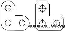
(Figure 1)
The structure of Fig. 2a is meaningful only when the batch is large, otherwise the cutting is troublesome during blanking. Therefore, the structure shown in Fig. B should be used in small batch production.
(Figure 2)
2. Material saving criteria (configuration criteria for punching parts)
Saving raw materials means reducing manufacturing costs. Bits and pieces of leftover materials are often treated as waste. Therefore, leftover materials should be reduced as much as possible in the design of thin plate components. The waste materials of punching and cutting shall be minimized to reduce the waste of materials. In particular, the effect is remarkable when cutting large quantities of components. The ways to reduce cutting corners are as follows:
(1) Reduce the distance between two adjacent components (see Figure 3).
(Figure 3)
(2) Cleverly arranged (see Figure 4).
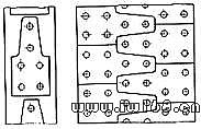
(Figure 4)
(3) Take out the material at the large plane and use it for smaller components (see Figure 5).

(Figure 5)
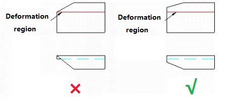
3. Sufficient strength and stiffness criterion
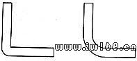
(1) the bending edge with beveled edge shall avoid the deformation area.
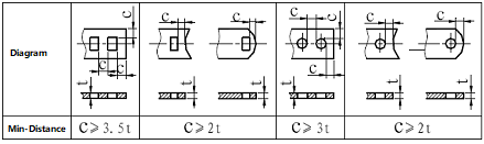
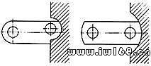
(2) If the distance between two holes is too small, cracks may occur during cutting.
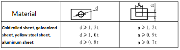
The punching design of parts shall consider leaving appropriate hole edge distance and hole spacing to avoid punching crack. The minimum distance between the punching edge of the part and the shape is limited according to the shape of the part and the hole. When the thickness t of the part is not less than the minimum punching distance from the edge of the material; When parallel, it shall not be less than 1.5T. See the table for the minimum hole edge distance and hole spacing.
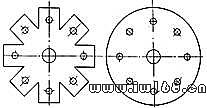
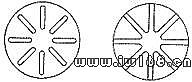
The round hole is the most solid in mold making, which is easy to manufacture and maintain, but the opening rate is low.
The opening rate of square hole is the highest, but the corner edge is easy to wear and collapse due to 90 degree angle, resulting in die repair and line stop The hexagonal opening has a 120 degree angle greater than 90 degrees, which is stronger than the square opening, but the opening rate is a little worse at the edge than the square opening.
(3) the rigidity of slender lath is low, and it is also easy to produce cracks during cutting, especially serious wear of cutting tools.
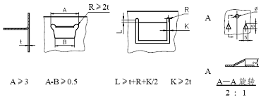
In general, the depth and width of the protruding or concave part of the blanking part shall not be less than 1.5T (t is the material thickness). At the same time, narrow and long cuts and too narrow grooves shall be avoided, so as to increase the edge strength of the corresponding part of the die. See Figure 8.
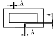
For brass and aluminum A≥1.2t; T-Material Thickness.
(Figure 8)
4. Reliable blanking criterion
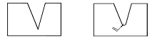
The semi-circular tangent structure shown in Fig. 9A is difficult to blanking. Because this requires accurate determination of the relative position between the tool and the workpiece. Accurate measurement and positioning is not only time-consuming, but more importantly, due to the wear and installation error of the tool, the accuracy usually can not meet such high requirements. Once the processing of such a structure has a slight deviation, the quality is difficult to ensure, and the cutting appearance is poor. Therefore, the structure shown in Figure B should be adopted, which can ensure reliable blanking quality.
(Figure 9)
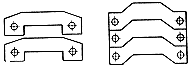
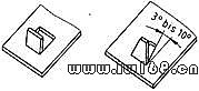
5. Criteria for avoiding sticking knife (configuration criteria for broken parts)
During blanking and cutting in the middle of components, there will be the problem of bonding and overlapping between tools and components. Solutions: (1) leave a certain slope; (2) The cutting surfaces are connected (see Fig. 10 and FIG. 11).
(Figure 10)
(Figure 11)
When lapping is made into 90 ° bend by punching in one process, pay attention to the material selection. The material should not be too hard, otherwise it is easy to break at the right angle bend. Process cuts shall be designed at the bending position to prevent cracking at the corner.
6. Vertical cutting surface criterion of curved edge
After the sheet is cut, it usually needs further forming processing, such as bending. The curved edge shall be perpendicular to the cutting surface, otherwise the risk of crack at the intersection will increase. If the vertical requirements cannot be met due to other restrictions, a fillet with a radius greater than twice the plate thickness shall be designed at the intersection of the cutting surface and the curved edge.
7. Gentle bending criterion
Steep bends require special tools and are costly. In addition, too small bending radius is easy to produce cracks and wrinkles on the inner surface (see FIG. 16 and FIG. 17).
(Figure 16)
(Figure 17)
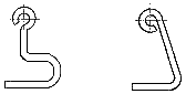
8. Criteria for avoiding small round crimping
The edges of thin plate components are often crimped, which has many advantages. (1) The rigidity is strengthened; (2) Avoid sharp edges; (3) Beautiful. However, two points should be paid attention to in crimping. One is that the radius should be greater than 1.5 times of the plate thickness; Second, do not be completely round, which is difficult to process. The crimping shown in Fig. 18B is easier to process than that shown in Fig. 18a.
(Figure 18)
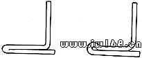
9. Groove edge non bending criterion
The bending edge and the edge of the slotted hole shall be separated by a certain distance. The recommended value is the bending radius plus twice the wall thickness. The stress state in the bending zone is complex and the strength is low. Slotted holes with notch effect shall also be excluded from this area. You can either keep the entire slot away from the curved edge or let the slot span the entire curved edge (see Figure 19).
(Figure 19)
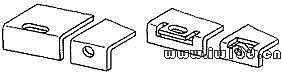
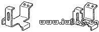
10. Combined manufacturing criteria for complex structures
For components with too complex spatial structure, it is difficult to form completely by bending. Therefore, the structure shall be designed as simple as possible. In the case of non complexity, composite members can be used, that is, multiple simple thin plate members can be combined by welding, bolt connection and other methods. The structure of Fig. 20b is easier to process than that of Fig. 20A.
(Figure 20)
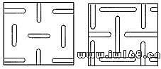
11. Avoid straight line penetration criteria
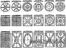
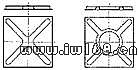
Thin plate structure has the disadvantage of poor transverse bending stiffness. Large plate structures are prone to buckling and instability. Further bending and fracture. The stiffness is usually improved by pressing grooves. The arrangement of pressure grooves has a great influence on the effect of improving the stiffness. The basic principle of pressure groove arrangement is to avoid the straight line connection in the area without pressure grooves. The through low stiffness narrow band is easy to become the inertial axis of the buckling instability of the whole plate. Instability always revolves around an inertial axis. Therefore, the arrangement of pressure grooves should cut off this inertial axis and make it as short as possible. In the structure shown in Fig. 21a, a plurality of through narrow strips are formed in the non pressure groove area. Around these axes, the bending stiffness of the whole plate is not improved. The structure shown in Figure 21b has no potential connected instability inertia axis. Figure 22 lists the common shape and arrangement of pressure grooves. The stiffness enhancement effect gradually increases from left to right. Irregular arrangement is an effective method to avoid straight-line penetration.
(Figure 21)
12. Connected arrangement criterion of pressure groove
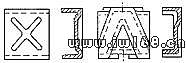
The low fatigue strength of the end point of the pressure groove is the weak link. If the pressure groove is connected, some end points will be eliminated. Figure 23 shows the battery box on a truck, which is subjected to dynamic load. The structure in Figure 23a has fatigue damage at the end of the pressure groove. This problem does not exist in the structure of figure 23B. Steep groove end faces should be avoided, and the groove should extend to the boundary if possible (see Figure 24). The penetration of the pressure groove eliminates the weak end. However, there should be enough space at the intersection of pressure grooves to reduce the interaction between pressure grooves (see Figure 25).
(Figure 23)
(Figure 24)
(Figure 25)
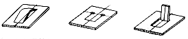
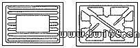
13. Space grooving criterion
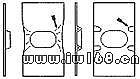
Therefore, the buckling resistance of the whole structure can not be improved only in one aspect. For example, for the U-shaped and Z-shaped structures shown in Figure 26, their instability will occur near the edges. The solution to this problem is to design the pressure groove into a spatial structure (see Figure 26b).
(Figure 26)
14. Local relaxation criterion
When the local deformation on the thin plate is seriously hindered, wrinkles will appear. The solution is to set up several small pressure grooves near the folds, so as to reduce the local stiffness and reduce the deformation obstruction (see Figure 28).
(Figure 28)
15. Configuration criteria of blanking parts
(1) minimum punching diameter or minimum side length of square hole
When punching, it should be limited by the strength of the punch. The size of the punch should not be too small, otherwise it is easy to damage the punch. See the table for the minimum punching diameter and minimum side length.
(2) Principle of punching notch
Sharp corners shall be avoided for punching notch as far as possible, as shown in Figure a. The form of sharp corners is easy to shorten the service life of the die, and cracks are easy to occur at the sharp corners. It should be changed as shown in Figure B.
R ≥ 0.5T (T – material thickness)
(Figure 1)
Related Posts


