Reasons for incorrect machining tooth profile angle
1. Incorrect knife tip angle
When grinding the turning tool, the tool tip angle is incorrect, that is, the included angle between the projection of the two cutting edges of the turning tool on the base surface is inconsistent with the tooth profile angle of the machined thread, resulting in the incorrect angle of the machined thread. Solution: When grinding the turning tool, an angle ruler or sample plate must be used to detect the correct tooth profile angle. The method is: parallel the sample plate or angle ruler to the front of the turning tool, and then check with the light transmission method. Common metric thread profile angle: 60 ° for triangular thread, 30 ° for trapezoidal thread and 40 ° for worm.
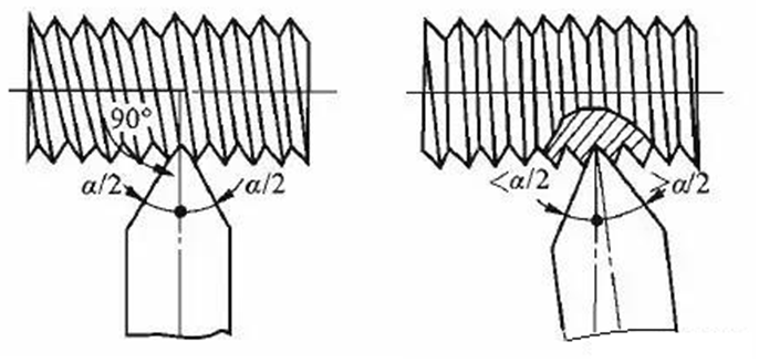
2. Radial forward angle not corrected
In order to smooth chip removal of the turning tool, reduce surface roughness, and reduce chip build-up, the radial rake angle is often grinded, which causes the cutting on both sides of the turning tool not to coincide with the axial direction of the workpiece, making the thread profile angle of the turned workpiece larger than the tool tip angle. The larger the radial rake angle, the more NC programming knowledge focuses on WeChat official account (NC programming teaching), and the larger the error of the profile angle is. At the same time, the thread profile turned is not a straight line but a curve in the axial section, which affects the fit quality of the thread pair. Solution: When turning threads with thread turning tools with large radial rake angle, the tool tip angle must be corrected by the included angle between the two edges of the turning tool, especially for threads with high machining accuracy. The correction calculation method is as follows:
tan ε r=cosrp.tan α
Where, ε R is the angle between the two edges of the turning tool; Rp is the radial front angle; α Is the tooth angle.
3. Excessive tooth profile angle during high-speed steel cutting
When cutting threads at high speed, because the extrusion force of the turning tool on the workpiece produces extrusion deformation, the processed tooth profile will be expanded, and the workpiece will swell at the same time. Therefore, when grinding the turning tool, the included angle between the two edges should be appropriately reduced by 30 ‘. In addition, the major diameter of the workpiece before turning external threads is generally smaller than the nominal size (about 0.13p).
4. Incorrect installation of turning tool
The improper installation of the turning tool means that the symmetrical centerline of the two cutting edges of the turning tool is not perpendicular to the axis of the workpiece, resulting in the inclination of the processed tooth profile angle (commonly known as chamfer). Solution: Use an angle ruler or template to install the turning tool so that the symmetrical center line is perpendicular to the workpiece axis, and the tool tip is equal to the workpiece center.
5. Tool wear
After the tool is worn, it is not timely sharpened, resulting in that the two sides of the processed tooth profile angle are not straight lines but curves or “rotten teeth”. Solution: reasonably select cutting parameters, and timely grind the lathe tool after wear.
6. Incorrect pitch (or lead)
(1) The full length of the thread is incorrect. The reason why the full length of the thread is incorrect is that the calculation or assembly of the exchange gear is wrong, and the position of the relevant handles of the feed box and slide box is wrong. The position of the handle of the feed box can be rechecked or the change gear can be checked.
(2) The thread is partially incorrect. The partial incorrect thread is caused by excessive movement of the lathe lead screw and the spindle, unbalanced rotation of the slide box handwheel, and excessive clearance between the opening and closing nuts. Solution: If it is caused by the axial movement of the lead screw, the adjusting round nut at the connection between the lathe lead screw and the feed box can be adjusted. More NC programming knowledge should focus on the WeChat official account (NC programming teaching) to eliminate the axial clearance of the thrust ball bearing at the connection; If it is caused by the axial displacement of the main shaft, adjust the nut after the main shaft to eliminate the axial clearance of the thrust ball bearing; If it is caused by poor engagement between the opening and closing nuts of the chute box and the different axes of the lead screw, the opening and closing nuts can be trimmed and the clearance between the opening and closing nuts can be adjusted; If the rotation of the chute box is unbalanced, pull out the hand wheel of the chute box to separate it from the rotating shaft and rotate evenly.
(3) During turning, the opening and closing nuts automatically lift, causing incorrect pitch. Solution: Adjust the opening and closing nut insert to reduce the clearance properly, control the lifting of the opening and closing nut during transmission, or hang a heavy object on the opening and closing nut handle to prevent midway lifting.
Related Posts


