Optimization scheme for efficient machining of aerospace aluminum alloy thin-walled parts (II): Improvement of machining process
2、 Process improvement
The main purpose of rough machining is to remove materials and leave appropriate allowance for finish machining. Therefore, rough machining generally does not need to consider the dimensional accuracy, surface quality and deformation of the workpiece. As long as the power of the machine tool allows, the production efficiency can be improved in many ways.
There are certain differences between finishing and rough machining of parts. In finishing, it is necessary to fully consider the influence of clamping, tool walking and process parameters on the internal stress of parts, as well as the influence of cutting force and cutting heat on the structure of parts during cutting, so as to control the deformation and avoid the deformation caused by the improvement of efficiency, resulting in the damage of part accuracy and surface quality.
2.1 cutting tools
Choosing more reasonable cutting tools can directly improve production efficiency. The cutting of aluminum alloy materials does not have high requirements for tool materials. Generally, cemented carbide milling cutter can be used, and the coating can be uncoated or diamond coating. In rough machining, because there is no need to consider the problems of accuracy and quality, the metal materials can be cut efficiently to the greatest extent. Therefore, large-diameter tools can be selected to reduce the times of tool walking and shorten the time of tool walking. In addition, in rough machining, try to choose dense tooth tools instead of sparse tooth tools, which can increase the feed per revolution, and the cutting speed can be increased at the same speed. In finish machining, in addition to the problem of efficient material removal, the problem of force and deformation control of thin-walled components in cutting should also be fully considered. K series cemented carbide tools (equivalent to the original tungsten cobalt in China, the main component is WC + CO, code named YG) should be selected for the finishing of aerospace aluminum alloy thin-walled parts. The rake angle of the tool should not be too small, otherwise the cutting deformation and friction will increase, the wear of the rake face will increase, and the service life of the tool will be reduced. The cutting test shows that the cutting force increases by 1% when the rake angle decreases by 1 ° in high-speed milling alcumgpb. It is generally recommended for this purpose γ 0 is about 12 °. The selection of tool back angle will affect the tool stiffness. In order to reduce the friction between tool and workpiece, the back angle must be larger. If necessary, double chamfered back angle can be used to increase the back angle and ensure the tool stiffness at the same time. The inclination of cutting edge affects the direction of chip outflow and the size of each cutting force component. A larger inclination of cutting edge should be selected in aluminum alloy cutting. It is generally recommended to use in high-speed milling of aluminum alloy λ S is 20 ° ~ 25 °. In addition, the arc radius of the tool tip should be selected appropriately, and the tool teeth should not be too dense, which is convenient for chip discharge, which is conducive to further improve the feed rate, prevent cold hardening layer and prolong the service life of the tool.
2.2. Tool path
A more effective way to increase speed and efficiency is to optimize the tool path. In high-speed cutting, it is necessary to ensure the directionality of the tool path, that is, the tool path should be simplified as much as possible, less turning points, the path should be smooth as much as possible and reduce rapid steering; Reduce the idle cutting time and increase the proportion of cutting time in the whole workpiece as much as possible; Loop cutting should be adopted as far as possible. By not interrupting the cutting process and tool path, the cutting in and cutting out times of tools should be reduced to obtain a stable, efficient and high-precision cutting process.
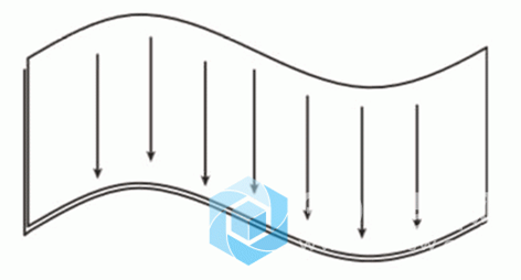
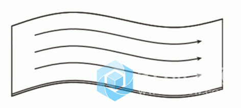
In the high-speed machining of large complex curved surface of aerospace integral structure, when the curvature of the curved surface changes greatly, the direction of the maximum curvature radius should be taken as the optimal cutting direction, as shown in Figure 5; When the curvature of the surface changes, the influence of the curvature radius on the cutting direction is weakened. It is advisable to select the cutting direction with the longest average length of a single tool path, as shown in Figure 6.
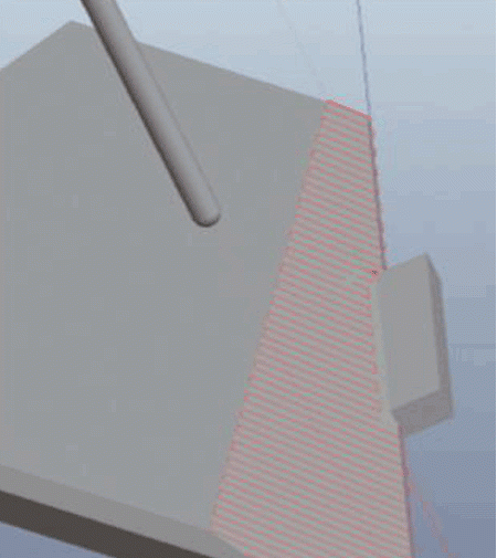
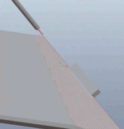
When machining the inclined plane, if the transverse horizontal tool walking shown in Figure 7 is adopted, the tool walking distance of each section is very short. During the cutting process, the main shaft needs frequent commutation, and the cutting stability is poor. Moreover, because the cutting is inclined plane, the horizontal tool walking needs the linkage of X or Y axis and Z axis, which is not conducive to the improvement of cutting speed. Therefore, for such inclined surface machining, the tool path should be arranged parallel to the longest inclined edge as far as possible (see Figure 8). Not only does the tool path have the longest and the number of commutations is the least, but also the single pass tool path is only in the XY plane for cutting, and the z-axis movement is arranged outside the workpiece contour. Even under high-speed cutting, the tool damage can be reduced.
2.3 cutting parameters
In rough machining, generally, large feed rate and appropriate large cutting depth can be selected, coupled with “high-power” high-efficiency cutting with medium cutting speed, which can achieve high material removal rate and greatly improve production efficiency. For finish machining, only increasing the speed and the number of teeth is feasible, and increasing the feed rate per tooth may reduce the surface accuracy, produce residual stress and lead to deformation. Therefore, “light cutting and fast cutting” with high cutting speed and low feed per tooth is often used to ensure the improvement of production efficiency and the accuracy and surface quality of products.
The cutting parameters can be finally determined through cutting finite element analysis and cutting test: using third wave advancededge software, simulation analysis and calculation are carried out for the power and torque requirements of machine tool spindle under different process parameters, and the optional range of spindle speed, feed per tooth and cutting depth of machine tool spindle can well meet the process requirements of high-speed machining of products is obtained. It provides guiding suggestions for the selection of cutting test parameters.
In the third wave advancededge software, the setting of workpiece material, tool material and coating, tool structure parameters and cutting parameters is completed through the new task, and the simulation is carried out to obtain the cutting torque demand curve under all cutting parameters. According to the data displayed in the curve, determine the maximum demand for cutting power and cutting torque under the current cutting parameters, and compare the actual performance parameters of the machine tool (motorized spindle torque and power diagram) to determine the compliance of the process parameters.
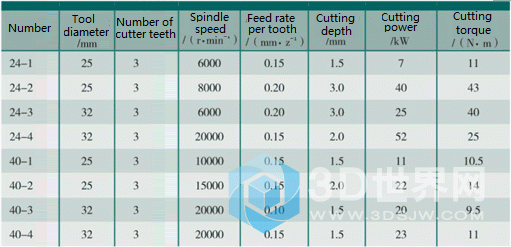
For example, the machining center with the maximum speed of 24000r / min carries out high-speed rough milling of 2219 aluminum alloy thin-walled structural parts. Indexable tools and uncoated fine grain cemented carbide blades are used φ 25mm、 φ The simulation calculation is carried out for two horizontal tool diameters of 32mm, and the results are shown in Table 1. Among them, tool No. 24-1 has a diameter of 25mm, the number of tool teeth is 3, the spindle speed is 6000r / min, the feed rate of each tooth is 0.15mm/z, and the cutting depth is 1.5mm.
Table 1 power and torque simulation results of high speed milling rough machining.
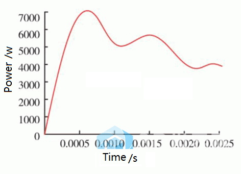
(1) The power demand is shown in Figure 9.
(2) The torque requirements are shown in Figure 10.
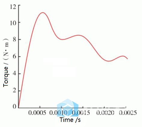
As can be seen from Figures 9 and 10, under the current cutting parameters, the maximum demand for cutting power is 7KW and the demand for cutting torque is 11n · M. The gantry high-speed machining center with the maximum speed of the machine tool spindle of 24000r / min has a maximum power output of 42kw (rated working condition S1) and a maximum output torque of 67N · m (rated working condition S1) at 6000r / min, which can meet the current processing requirements.
Through the confirmation of 8 groups of simulation results, it can be found that in order to make the machining power and torque of the machine tool meet the requirements of cutting parameters, the cutting tools and cutting parameters must be reasonably selected, as shown in Table 2.
Table 2 power and torque demand analysis of machine tool.
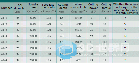
In the existing gantry CNC machining center, the maximum speed of the machine tool spindle is 24000r / min. in the rough machining process of thin-wall panels, if it is selected φ 25mm or φ 32mm indexable cutter, for the optimization of cutting parameters, the spindle speed should be appropriately increased, and the selection range is 12000 ~ 15000r / min; The feed rate and cutting depth of each tooth shall not be too large, and the selectable ranges are 0.15mm/z and 2 ~ 3mm respectively.
The cutting test can be designed within the optional range of the parameters obtained from the finite element analysis, and the optimal cutting parameters can be selected by taking the cutting efficiency, surface roughness and machined surface morphology as the evaluation criteria.
Related Posts


