Laser welding of metals and plastics: how to achieve maximum efficiency?
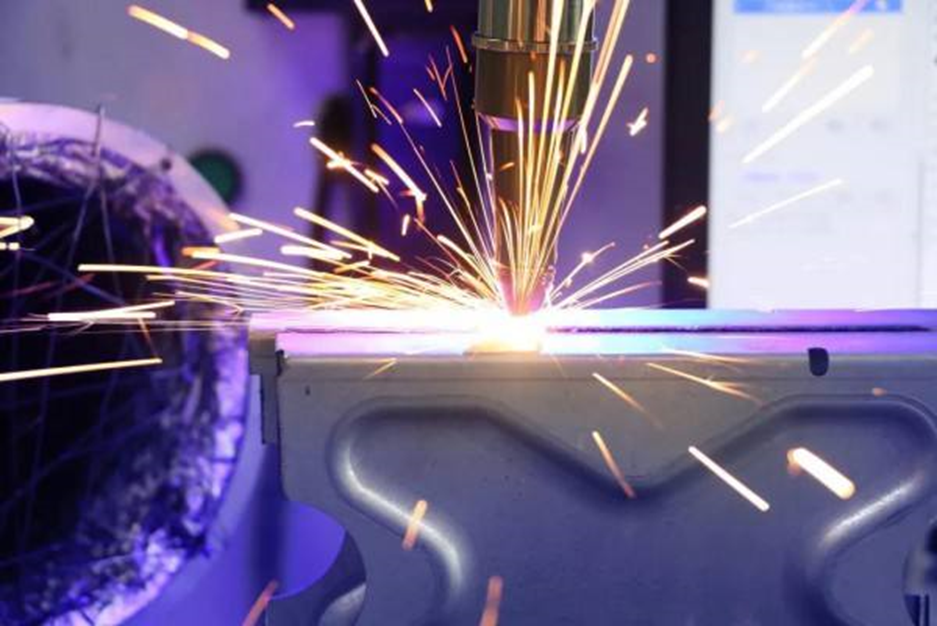
Nowadays, in more and more industrial applications, lasers have been seen as an alternative solution for welding plastics/composites directly to metals. This non-contact processing method provides the highest process flexibility.
At present, one of the driving factors in the automotive industry is how to make lighter cars without increasing costs or causing damage or impact on performance, quality and safety. For seat structures, this mainly includes the use of thin, higher strength steel. In recent years, mixed material structures have also been widely studied. This also applies to metal only hybrid structures and component structures made of metal/plastic composites.
The use of these hybrid material structures presents many different challenges, most notably how to weld together the constituent materials with different chemical, mechanical and thermal properties. At present, the most traditional technologies used to weld plastic and metal materials are adhesive bonding, mechanical welding, cladding molding or a combination of these processes. Such means involve a large number of assembly operations and will result in design restrictions.
Nowadays, in more and more industrial applications, lasers have been seen as an alternative solution for welding plastics/composites directly to metals. This method does not require additional liquid/solid adhesives or assembly components, and provides high process flexibility compared to mechanical joints and complex and expensive molds. In order to evaluate the possibility of this new laser technology, Faurecia Automotive Seating of Germany and the European Community jointly funded a project called PMjoin.
Laser process steps
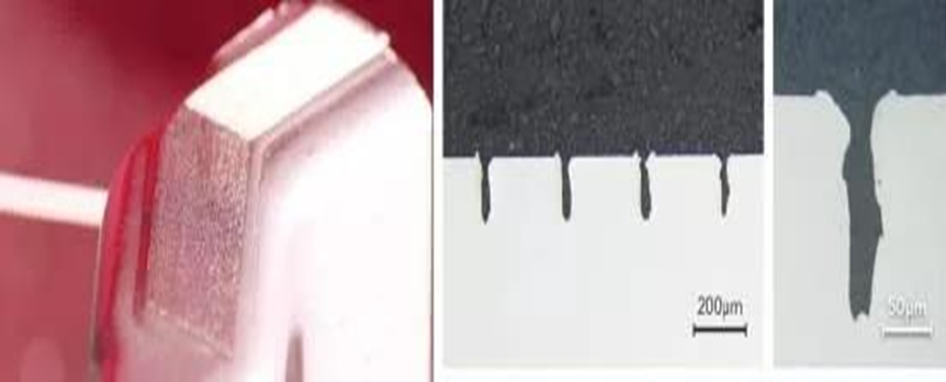
This direct, non-contact laser process includes two steps. First, by scanning the area and ablating the material locally, a grooved microstructure is formed on the metal surface. The grooves can be as small as a few microns wide, and the depth can be changed by scanning the laser multiple times in the same area. Figure 1 shows two different groove geometries: the top is made of a continuous wave (CW) single-mode fiber laser, which is characterized by an irregular cross section groove with a small recast structure at the top, and the bottom is made of a nanosecond pulse laser, which is characterized by a regular groove shape with a large recast structure at the top.
In the second step of the method, the plastic is overlapped with the structured metal and heated to the melting temperature. For plastics that are transparent to the laser wavelength, the laser beam can be applied from the side of the plastic – the laser energy is transmitted to the joint interface through the plastic, and the energy at the interface is absorbed by the metal. The metal gradually heats up, and the low thermal conductivity of the plastic ensures local hot spots, melting the plastic.
For plastics that are opaque to laser wavelengths (including most automotive structural plastics/composites), they must be heated from the metal side by electrically heating the metal. When sufficient heat is generated locally at the interface, the plastic will melt. In both cases, good temperature control is essential to avoid overheating (leading to pores) or burning of the plastic.
Although conductive heating solutions do not save energy, they are as effective as transmission heating solutions that create stable joints. In this process, a continuous wave direct diode laser is used to conduct conductive heating from the metal side. In the process of conductive heating and transmission heating, pressure must be applied to ensure that the heat is effectively transferred to the plastic. Once the plastic reaches the melting temperature, it flows into the microstructure under pressure. When it cools, it fixes itself in the metal structure, thus forming a mechanical interlock.
Car seat design concept
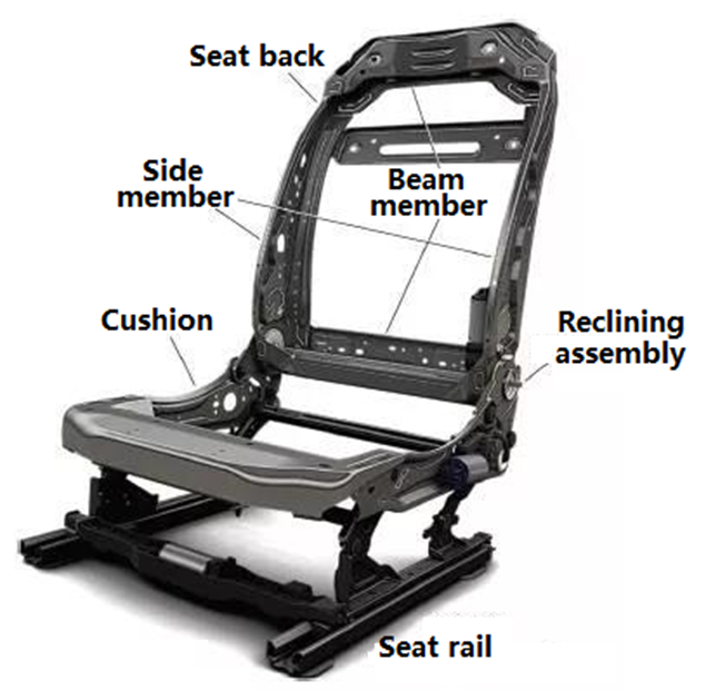
As a part of the PMjoin project, Faurecia has designed a conceptual seat back structure based on its general steel seat structure (Figure 2). The two high-strength steel side beams of the seat back are replaced by PAGF30 composites. The upper and lower cross beams and reclining components of the backrest, as well as the seat cushion and adjusting guide rail structure remain unchanged.
In the first part, the influence of microstructure parameters on the mechanical properties of the joint is studied. For this reason, a set of test design was arranged to produce simple specimens with various groove patterns, and then tensile shear, tensile and peel tests were carried out on the specimens. The parameters studied include the number of repeated (laser) runs, structure density (spacing between grooves), the angle of groove relative to the material surface, the orientation of groove structure relative to the load direction, laser type, and laser power. For example, a simple groove geometry can be used to achieve a shear strength value of 17N/mm2, which is more than twice the value achieved by a rough (sandblasted) surface and 4 times the value of an untreated metal surface.
At present, it has been found that different groove geometries can be achieved using different (structured) lasers. The irregularity of the groove shape and the size (and shape) of the recast layer protruding from the material surface help to anchor the plastic in the joint.
In the second step of the study, the results of the small-scale test were transferred to the concept seat back structure. The mechanical load of each welding point, that is, the welding between the upper and lower cross beam components and the composite side beam components, and the welding between the steel leaning components and the composite side beam components, is determined through the finite element (FE) analysis of a representative steel structure. Based on the results of small-scale tests, the required joint area for load transfer calculated by FE is determined at each joint.
Due to the use of the composite side member from the previous project, the welding points need to be slightly redesigned to ensure that the new laser based technology can obtain sufficient welding area. In addition, a new steel support was designed and fabricated to weld the existing reclining assembly to the composite side member. At the same time, also designed a suitable positioning and clamping fixture.
test result
Using the parameters determined in small-scale test, a small part of the conceptual seat back structure was made, and the quasi-static front impact, rear impact and dynamic front impact tests were carried out. Both types of tests are helpful to understand how failures in structures are presented, and dynamic impact tests show what actually happens in real life. Although the latter only gives a qualified or unqualified report, the quasi-static impact test also returns a quantitative result – that is, under what torque or force conditions the structure will fail.
Although positive as the first test result, the observed failure modes also indicate that the design concept is still too rigid. In addition, the potential of redesigning steel and composite components to maximize their effectiveness on the structural performance of the seat back and thus achieve more advanced design remains to be explored. In any case, this hybrid structure passed the dynamic impact test.
This conceptual study clearly shows that using lasers to weld plastic directly to metal is an ideal solution to replace traditional means such as adhesive bonding, mechanical welding or cladding. Based on this result, the semi-structured hybrid components can now efficiently use this laser welding technology.
However, there is still a way to go before mass production of structural hybrid components. This requires at least another design iteration to maximize the potential of the mechanical strength process of the two materials and structures, and to evaluate the impact of long-term variables such as humidity and temperature on performance. In addition, other alternative technologies for conductive heating can also be considered.
Related Posts


