How to match the cutting tool with the machine tool
As a tool directly or indirectly installed on the machine tool to complete the workpiece processing task, we must consider two applicability and one matching. That is, it is applicable to the selected machine tool, the selected workpiece, the processing task and the matching with the machine tool. However, this paper mainly discusses how to grasp the matching between the tool and the machine tool from the matching of the tool.
When it comes to the matching of tools and machine tools, you may first think of the matching of shapes and dimensions. Indeed, the matching of the shape and size is the basis for the correct installation of the tool on the machine tool. Without this foundation, the tool cannot be correctly installed on the machine tool, so it is impossible to complete any machining task.
However, this is not enough.
After the tool is installed on the machine tool, it needs to complete certain processing tasks. In the process of completing this machining task, it is necessary to ensure machining accuracy, bear and transfer cutting force and cutting torque, bear, transfer and export cutting heat, consider possible transmission of cutting wastes (chips and heads) and even workpieces, and digital transmission of modern tool parameters.
Although some of these tasks are not common, they are also tasks that the tool may undertake. If we can consider the tool selection and the matching between the tool and the machine tool, it will increase our thinking to solve the processing problems.
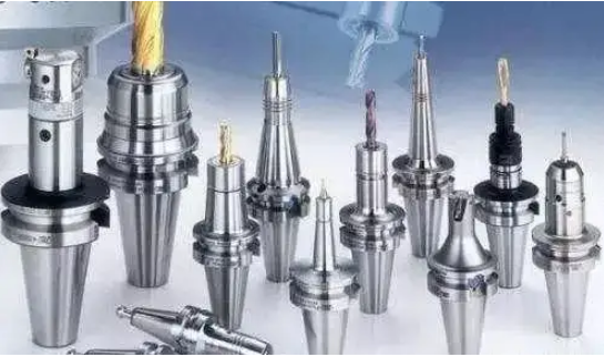
Ensuring machining accuracy, transmitting cutting force and torque, and providing channels for cutting fluid are the problems we often encounter after ensuring the matching of shape and size. For example, on machining centers, we often use cylindrical (usually called straight handle) as the clamping method. As for the cylindrical tool shank, in addition to the typical complete cylinder, there are also some changes that add some other elements to the cylinder, such as flattening straight shank (the milling cutter is divided into single cutting plane and double cutting plane according to the diameter, and the common full cutting plane is called side pressing type), oblique flattening type with 2 ° inclination, straight shank with flat tail (commonly used for drill), straight shank with square body (commonly used for tap and reamer) and other methods.
As far as the connection mode between this kind of tool shank and the machine tool is concerned, only the cylindrical part is used for positioning and clamping. The spring sleeve system of various pressure angles, the powerful chuck system, the hydraulic locking system, the thermal expansion clamping system, and the force deformation locking system are all used to lock the cylindrical tool shank. However, various clamping methods have advantages and disadvantages. Take the most common spring sleeve system as an example. A large pressure angle (here, the pressure angle is defined as the angle between the positive pressure of the conical surface locking and the cylinder axis), that is, a large taper angle represents a short locking stroke, which is conducive to fast locking and loosening. However, under the same locking torque, the positive pressure decomposed to the cylindrical surface is small, and the resulting friction distance is small, and the cutting force distance that can be resisted is correspondingly small, The tool is prone to slip in the tool shank, which affects the stability of the machining process and the quality of the machined surface; At the same time, the diameter of the tool shank that can be clamped by this kind of chuck varies greatly, which is conducive to reducing the inventory of the spring sleeve and optimizing the management. While small pressure angles are opposite. The spring sleeve with small pressure angle can clamp the tool shank with a small diameter range, and the locking stroke during clamping is long, which is not conducive to rapid clamping and loosening. However, its clamping accuracy is slightly higher, the clamping force is large, and it can withstand greater cutting load. It is a technical activity to grasp the matching of cutting tools and machine tools.
The hydraulic locking system is a new clamping system. It uses the incompressibility of high viscosity hydraulic oil to make the inner wall of the tool clamping cavity elastically deform and lock the tool. The hydraulic locking system has high accuracy, and it is convenient to lock and loosen without special equipment. The locking torque is usually better than the spring sleeve system, but its inner wall can only work within the range of elastic deformation. Once beyond this range, the inner wall will undergo irreversible plastic deformation, which will cause permanent failure of the tool holder clamping cavity. Therefore, the flat tool shank, especially the full flat tool shank commonly used by drilling tools, cannot be used in the hydraulic locking system. Cavity pressure and tool handle not inserted into the bottom of the cavity are also common causes of damage and failure of the system.
The thermal expansion clamping system usually requires special equipment, which is preferably capable of controlling heating and cooling according to a variety of predetermined modes. Non professional heating equipment (even flame heating) may be used, but often due to the temperature and heating curve can not be well controlled, other parts of the tool shank are affected, and even the metallographic structure is changed, so that the system will fail quickly. In addition, the tool length of the thermal expansion clamping system is difficult to adjust, and special auxiliary tools are required, which adds some troubles to the occasions where multiple tools need to work synchronously. The above are some knowledge points about the matching of tools and machine tools.
On the other hand, the tool clamping mode may also determine the possible value of production efficiency.
The cylindrical tool shank, hydraulic pressure and thermal expansion are balanced designs that can adapt to higher rotational speeds, while the flattened clamping is a typical unbalanced design, which is not recommended for high-speed cutting by tool manufacturers.
As for the tool shank itself, when a part of the material is milled (or ground) to form a pressure surface, the center of gravity of the tool shank is not coincident with the rotation center of the tool. In the process of tool clamping, the leveling handle is pushed to the side that has deviated from the center by the locking screw, and the center of gravity of the tool will further deviate from the rotation center of the tool on the machine tool, which increases the imbalance of the tool. In addition, some users do not care about the length of a screw after the original locking screw is damaged or lost. This behavior also adds uncertainty to the balance performance of the tool. Therefore, it is not recommended to use the flattening type (including oblique flattening) at high speed.
However, the flattened type is a tool shank with forced driving property, which is more reliable than the pure cylinder driven by friction under high torque. Therefore, it is suitable for rough machining (rough machining generally has a large torque but a low speed). In short, to grasp the matching between tools and machine tools, we need to start with both tools and machine tools.
Related Posts


