Control of springback of U-shaped bending parts and improvement of die design
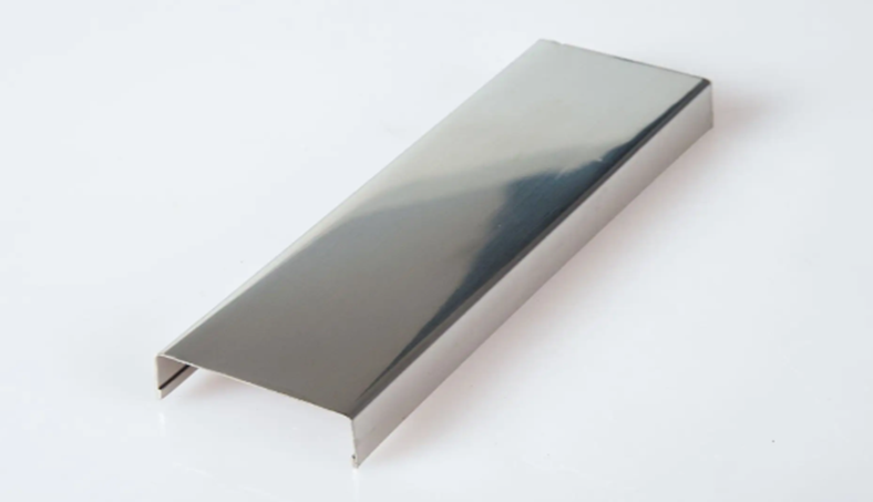
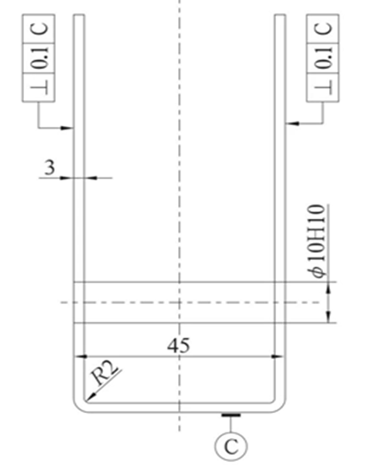
Figure 1 shows the structural diagram of U-shaped bending piece, which is made of 3mm thick 60Si2MnA spring steel. Due to the functional requirements, the bent arms are required to be perpendicular to the bottom plane, and the perpendicularity is required to be 0.1mm φ The 10H10 hole is coaxial.
Process analysis and scheme determination
The shape of the part is not complicated, and the shape is U-shaped structure. It is only a composite part of blanking and bending, with 2 parts φ 10H10 hole is of ten grade accuracy, which can be ensured by stamping; By analyzing the technical requirements of the parts, it can be seen that the key and difficult points in the processing of the U-shaped bending parts are mainly the form and location tolerance requirements of the perpendicularity of the bent straight arm and the bottom plane of 0.1mm, and two φ Coaxial requirements for 10H10 holes.
Taking into account the use of correction, adjustment of the positioning of U-shaped bending parts and other measures, the bending rebound can be controlled respectively to ensure two φ For the coaxial requirements of 10H10 hole, it was decided to design a special bending die to complete the above processing requirements. The whole part processing process plan is: die cutting part shape (including 2- φ 10H10 hole) → bending parts → correcting each bending straight arm to ensure the perpendicularity requirements.
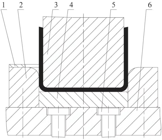
In order to complete the part processing, it is necessary to design two sets of die for shape blanking and U-shaped bending. As the structure of the part shape blanking die is relatively common, it will not be detailed here. The U-shaped bending die designed consists of upper die and lower die, and its structure is shown in Figure 2.
In the design of the U-shaped bending die, in order to ensure that the straight arm of the bent part is perpendicular to the bottom plane, the one-sided clearance between the working parts of the punch and the die is 2.8 2.9 mm; In order to increase the compression and forming force of the parts and reduce the bending rebound of the parts, the die is placed on a 300t four column hydraulic machine for processing. During operation, the press ejector cylinder pushes the ejector plate 4 to be flush with the upper plane of the female die 2 through the ejector rod 5. At this time, the semi-finished products cut will be placed in the locating plate 1 at an appropriate position on the upper plane of the female die 2. With the decline of the press, the punch 3, the ejector plate 4 and the female die 2 will work together to complete the U-shaped bending of the parts.
Production and cause analysis of processing defects
After the above mold design and manufacturing, the mold was tested, and the bent parts generally had inconsistent left and right heights. The perpendicularity between the upper part of the bent U-shaped straight arm and the bottom plane was about 3mm. After adjusting the position of the positioning plate 1 and the clearance between the two sides of the mold, the consistency of the left and right heights of the part contour was controlled to a certain extent, but still could not meet the product requirements. The perpendicularity between the U-shaped straight arm and the bottom plane was still about 2mm, and the bending fillet was not clear.
In view of the above defects, after on-site observation and analysis, it is believed that: due to the high strength of 60Si2MnA, the incompletely consistent fillet radius of the two bending parts of the female die, the uneven die clearance, the anisotropy of materials and other factors, the unbalanced force of the part during bending, the inconsistent bending deformation of both sides, and ultimately the deviation and rebound of the part.
After taking measures such as further reducing the gap and trimming the fillet radius of the bending part for the die, the force on both sides of the part bending cannot be balanced during the bending deformation. Therefore, although the verticality after bending has been improved to a certain extent, it still needs to be adjusted to meet the product requirements, and the production efficiency is low.
Improvement measures
In order to completely solve the above quality problems, the following improvement measures were adopted in the process.
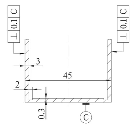
After negotiation with the product designer, the structure of the part is properly improved. Two 0.3mm deep and 2mm wide long grooves are set at the bending U-shaped fillet radius to reduce the bending rebound of the part. The improved structure diagram of the part is shown in Figure 3.
By properly improving the structure of the bending die and reducing the possible deviation of the parts during the bending process, 2 points can be ensured φ Coaxial requirements for 10H10 holes. The whole part processing process plan is improved to: die cut part shape (including 2- φ 10H10 hole) → bend and correct parts.
Mold improvement
Improved die structure
According to the improved structure of the parts, the original U-shaped bending die is improved to a grooving bending compound die, and the structure is shown in Figure 4.
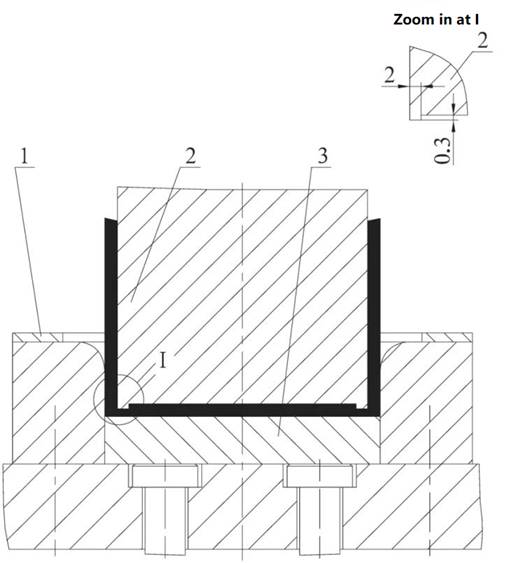
1-locating plate 2-notching bending punch 3-ejector plate
The working principle of the mold is: the whole set of mold is still processed on a 300t four column hydraulic press. As the slider of the press rises, the mold opens, and the upper and lower molds are separated from each other. The press ejector cylinder pushes the ejector plate 3 to a position 2mm above the upper plane of the mold through the ejector pin. At this time, the semi-finished product that has been punched is placed in the locating plate 1 at an appropriate position on the upper plane of the female die. The press descends. The notching bending punch 2 and the ejector plate 3 first form the two long grooves on the semi-finished product. As the press continues to descend, the notching bending punch 2, the ejector plate 3 and the female die work together to complete the U-shaped bending and final correction of the part. As the slider of the press rises, the upper and lower dies begin to disengage, The bent parts are ejected from the cavity of the concave mold through the ejector plate 3. At this point, the parts work in place and turn to the next work cycle.
Key points for improvement
To ensure bending φ The 10H10 hole center is concentric. Replace the locating plate 1. The new locating plate 1 is positioned in full shape with the outer arc of the part. The problem is solved by precise positioning and adjustment of the part.
In order to solve the possible deviation of the working parts when the die is bent, replace the punch with a notching bending punch. See the enlarged drawing at I in Figure 4 for the specific structure, and machine a fine and dense tooth surface on the bottom plane of the punch.
In order to increase the pressing force on semi-finished blanks during the long groove pressing process, replace the top plate 3. The new top plate is 2mm thicker than the original top plate. At the same time, fine and dense tooth surfaces are machined on its upper plane.
The one-sided clearance between the male die and female die working parts of the whole die is still 2.8 2.9 mm.
Concluding remarks
After the above improvements, the parts produced according to the improved processing technology meet the drawing requirements. At present, the mold works well and the product quality is stable.
As the part processing is mainly completed by the mold, and the part processing quality is mainly guaranteed by the mold, this process improvement scheme has greatly improved the production efficiency on the one hand, and guaranteed the product quality on the other hand.
Related Posts


