Analysis of Turning Methods for Precision Disk Parts
1、 Part process analysis
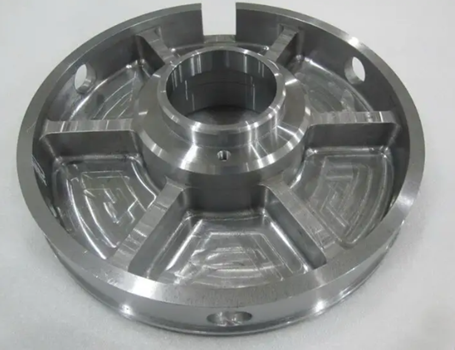
Since this part is a tool for balancing parts, the runout of all surfaces is required to be no greater than 0.02. Therefore, two aspects should be guaranteed in the process: 1. Machining accuracy. 2. Prevent machining deformation. The following two aspects are analyzed and discussed:
① Considering the high processing requirements, the turning process can be divided into three steps. The first step is rough machining, with 0.5~1mm left on one side. The second step is finishing after heat treatment.
② For other surfaces, the inner hole shall be considered as the benchmark for finishing. Both sides can be polished. The drawings shall be processed based on this surface and inner hole to ensure dimensional tolerance.
2、 Material selection:
As the drawing requires 20 # material to be carburized. But it is very difficult to process. Therefore, it is changed to material 38crmoal (nitriding treatment) during processing. Change the processing method to reduce the processing difficulty.
Hardening and tempering treatment shall be carried out after rough machining, and semi finishing shall be carried out. 0.5~1mm can be left for each drawing, and 0.5~1mm for each side of each hole. The method of stress relieving and tempering shall be adopted before finishing. Except for holes requiring high accuracy, they are all machined to size. Theoretically and practically, 38crmoala nitrogen coating shall not be greater than 0.005mm. After nitrogen coating, finish machining each hole to ensure the drawing requirements.
3、 Processing method:
1. Due to the large size allowance of the blank, during rough machining, use a three jaw chuck to clamp the outer diameter of the part, and take the left end face of the part and the outer diameter of the blank as the rough benchmark for processing. The lathe rotates at 120 rpm, the cutting amount is 0.4 ㎜/s, and the cutting depth is 3 ㎜. In terms of tool selection, 45 ° excircle deflection tool shall be selected, and the front angle of turning tool shall be smaller, generally 2 °~ 3 °, and the rear angle shall be 3 °~ 5 °. At the tool tip, a circular arc of r0.5-r0.8mm shall be ground, and a transition edge of 0.1-0.2 shall be provided at the blade, so as to increase the strength and durability of the tool. The tool material is yg8 or yg6 tungsten cobalt cemented carbide, which is characterized by good toughness, wear resistance and impact resistance.
2. After rough turning, the parts shall be subject to heat treatment, semi finish turning and low temperature tempering in the heat treatment process to eliminate the machining stress generated in the parts during the machining in the previous process. Prevent elastic deformation of parts.
3. After the above processes are completed, it will enter the finishing stage.
In order to prevent internal stress caused by machining parts, lathe grinding tools are used and grinding wheels are used instead of carbide turning tools, thus greatly reducing the machining stress caused by cutting and deformation caused by chip heat. Moreover, the surface roughness of fixture grinding tools is less than that of turning tools, thus ensuring that the surface roughness of parts is ra1.6 and ra0.8.
Since this process is a finishing process, the selection of the benchmark is important. According to the principle of benchmark coincidence, in the finishing process, select “A” as the positioning benchmark, and “51.5” as the auxiliary benchmark. In terms of tool selection, yt15 carbide turning tool is used. The rake angle of the tool is 8 °~ 10 °, the rake angle of the tool is 3 °~ 5 °, the arc at the tool tip is 0.1 ~ 0 mm, the edge inclination is 10 °~ 12 °, and the main deflection angle is 90 °. The lathe speed is 160 rpm, the turning tool amount is 0.05 mm/s, and the feed rate (f) is 0.01 mm
First, clamp the outer diameter of the part with a sector soft jaw, align the inner hole and 51.5 right end face with a dial indicator, and ensure that the concentricity and perpendicularity are both 0.01, then machine m140 first × 1.5 Triangular thread with machining allowance. Secondly, use 90 ° external eccentric tool, r3 arc turning tool and internal hole turning tool to process each surface, leaving 0.2mm allowance. Replace m140 × 1.5 Thread shall be turned out with m140 × 1.5 The thread gauge shall be inspected, and the next process can be carried out only after it is qualified.
because φ 152 and φ 129.975 After the internal and external surfaces are machined, the three jaw chuck is used for clamping. Because the thin wall of the part is easy to produce plastic deformation, which seriously affects the processing quality of the part, a round bar with an outer diameter and a clearance of 0.01 mm and a length of 34 mm is turned. Wrap with 0.5mm thick and 20mm wide copper sheet φ 152 outer diameter to prevent chuck from damaging parts and affecting surface roughness. Clamp with four jaw chuck φ 152 outer diameter, use a dial indicator to align the inner hole and 51.5mm left end face, and ensure that the concentricity and perpendicularity are 0.01. After clamping, use the excircle carbide finish turning tool yt15 with the main deflection angle of 90 ° to machine the outer diameter, use the r3 arc turning tool to machine the 24mm right end face and the r3 arc, and then use the internal hole turning tool to machine the 3 × 60 ° chamfer.
Install the prepared lathe grinding tool on the tool holder, and install the grinding wheel. The spindle rotation is 36 rpm, and adjust the positive and negative rotation of the grinding wheel. Use the sector soft chuck to clamp the parts. Pay attention to the proper clamping force, which is easy to deform the parts. Because the force on the parts to be ground with lathe grinding tools is small, the clamping force can be relatively small to prevent deformation. After clamping, use a dial indicator to align the inner hole and the 51.5 size right end face, and ensure that the concentricity and perpendicularity are both 0.01. Grinding with grinding wheel φ 289、 φ 152 and 4.5 right end faces, meeting the drawing requirements.
Related Posts


