Advanced Induction Hardening and Tempering Technology of Non rotating Crankshaft in America
A new process of induction heat treatment for crankshaft is introduced, which is different from the conventional process and does not rotate the crankshaft. Compared with the operation of traditional induction hardening equipment, this paper summarizes the technical advantages of this new static method, namely, saving cost and space.
Crankshafts are widely used in internal combustion engines, pumps, compressors, etc., and belong to the most critical type of components, especially for engines with a mass between 15 and 40 kg. At the same time, the same is true for some crankshafts with a mass of more than 700kg (crankshafts for fixed engines used in shipbuilding or thermal power generation).
An engine crankshaft, especially a cast or forged piece, consisting of a series of crank pins and main journals connected by a crank arm/counterweight. Steel forgings, ductile iron castings, microalloyed forgings and austenitic bainite ductile iron castings are the most commonly used crankshaft materials. Some of the most important requirements of the crankshaft are: high strength and elasticity, good fatigue and wear resistance, good stiffness, light weight, low noise and torsional vibration (NVH characteristics), high geometric accuracy, short length, high bearing capacity and low cost at low speed torsion. Heat treatment plays an important role in crankshaft manufacturing quality.
Conventional techniques for crankshaft rotation
Most of the existing crankshaft induction hardening equipment require the crankshaft to rotate during the heating process. When the crankshaft rotates around the main axis, each crank pin and main journal is heated by a U-shaped sensor close to the surface of the crank pin and main journal. Since the crank pin axis is in the radial direction of the main axis, the crank pin will run around the main axis. The rotation speed of the crankshaft generally varies between 24 and 32 r/min. Therefore, U-type inductor and some other rather heavy parts of induction hardening equipment (including power supply output transformer
Compressor, water-cooled coil, bus coil, cable, etc.), which usually weighs more than 900kg, must move with the rail of the connecting rod journal. The circular track motion of the heavy system must be kept very accurate. All these factors cause the design of conventional induction hardening equipment to be quite complex, sensitive, bulky, noisy and expensive.
Maintainability, reliability and repeatability of hardening mode of equipment are also the concerns of conventional technical users. In particular, the short service life of the coil has always been a problem. Generally, the service life of the “U” coil is less than 2-3 weeks. When using the existing rotary crankshaft quenching technology, there are several factors that lead to the short service life of the coil:
(1) Conventional technology requires that the gap between the coil and the surface of the heat-treated workpiece is very small (sometimes less than 0.5mm). The narrow gap, relatively long heating time (7~12s), crankshaft surface temperature (above 950 ℃) and humid working environment all provide favorable conditions for stress corrosion of copper coils.
(2) The complex geometry of the brazing coil has many joints. In addition, the existence of a large amount of heat and electromagnetic force provides favorable conditions for stress fatigue, coil failure and crack propagation, especially in the brazing joints where the heat of the induction coil is concentrated.
(3) Due to the narrow gap, the coil often accidentally collides with the surface of the rotating crankshaft (the coil “sits” on the crankshaft journal), so the damage of the coil (excessive use of the coil) often causes premature failure of the coil. This phenomenon is caused by the uncontrollable wear of the cemented carbide guide (positioner), or in other aspects, such as the error of the non-contact coil position tracking system.
A new static quenching process for crankshaft
In order to avoid the shortcomings mentioned above and solve other problems concerning the conventional quenching process of crankshaft rotation that users are concerned about, Inductoheat Company in Madison Height, Michigan, USA, has proposed a new non rotating technology.
The crankshaft static quenching process does not need to rotate or move the inductor or crankshaft during the heating and quenching cycle, and does not need high current contact when using the annular clamping type coil. The first machine has been manufactured and used in a world leading automobile manufacturer, and the second machine is close to completion.
The advantages of the non rotating hardening system are immediately recognized by the user’s material experts, manufacturing engineers and quality experts. Some characteristics of the system are described below.
Static heating methods that do not require crankshaft rotation have several practical benefits, such as simple operation, high reliability, maintainability, compactness (only 20% of the floor space required by conventional processes), and cost reduction. According to the user’s requirements, the crankshaft can be operated and heat treated vertically or horizontally.
The reduction of overall dimension deformation is always one of the most critical factors in heat treatment of crankshaft, because it directly affects the amount of metal removed by grinding. There are several factors affecting crankshaft deformation, including material properties, hardness distribution, residual stress, etc. One of the most important factors is the total heat generated inside the crankshaft (including the main journal, crank pin and balance weight). The greater the amount of heated metal, the greater the metal expansion, resulting in greater deformation.
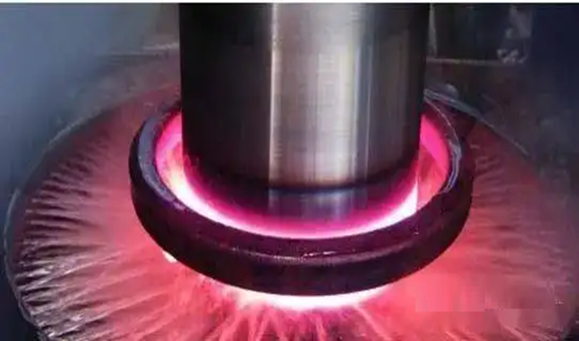
One of the remarkable advantages of the crankshaft static quenching technology is that the heating time is short, generally between 1.5~4s (compared with 7~12s of the conventional process). Due to the short heating time, only a small amount of metal is heated. The minimization of its heat affected zone leads to the minimization of metal expansion, which significantly reduces the changes in size and shape (generally the deformation is less than 0.025 mm), thus reducing the requirements for grinding.
Due to the short heating time, the crystal growth, decarburization and oxidation on the surface of the crank pin and main journal are reduced, and the metallurgical properties of the hardened area are improved. This hardened zone is clearly defined and “has a clear boundary”, so there will be no “fuzzy transition zone” due to long heating time. This zone is composed of fine grain martensite microstructure with a small amount of residual austenite. There is no free ferrite. In the conventional process, when users study the hardness distribution, they often observe a critical amount of free ferrite. Its presence on the surface of the crank pin and main journal is harmful to the wear resistance and other important characteristics of the crank pin and main journal.
The short heating time can also produce the phenomenon commonly called “induction superhigh speed hardening”. At this time, the hardness is 2~4HRC higher than the normal maximum hardness of the given steel grade. This allows the user to use a lower steel grade (lower carbon content) without losing the expected surface hardness and hardness distribution of the product.
In terms of electromagnetism, any heating part of the crankshaft (main journal, crank pin, oil seal) regards the crankshaft static quenching process inductor as an annular closed coil, and the induced eddy current flows around the heat treatment part (with a common eddy current ring). On the other hand, when the conventional U-shaped induction coil design method is used, the heat source is limited to the local eddy current itself, which leads to the reduction of the coil efficiency, especially above the Curie temperature. Therefore, the electrical efficiency of crankshaft static hardening process coil is higher than that of U-shaped coil. In addition, compared with the conventional technology, the sensitivity of the crankshaft static hardening process coil to the change of the gap between the workpiece and the coil will be greatly reduced, and a larger gap will be allowed between the coil and the journal surface.
The crankshaft static quenching process inductor is regarded as a traditional annular cylindrical coil in the heating part of the crankshaft (main journal, crank pin, oil seal). Thus, symmetrical heating is produced and the hardness distribution is more uniform. On the contrary, when U-shaped coils are used, there is no symmetrical heating mode, and only half of the crankshaft (i.e. main journal or crank pin) is heated at any given time. The other half of the crank pin and main journal is in the “wet cooling” mode. The unsymmetrical heating performance of the U-shaped inductor will lead to uneven hardness distribution and possibly elliptical deformation of the heated workpiece.
Since the heating time of the crankshaft static quenching process is only one third to one fourth of that of the conventional process, the thermal efficiency of the coil will also be enhanced (radiation and convection losses will be reduced) when new technologies are used. The crankshaft static quenching technology is not very sensitive to the irregular shape of the adjacent objects (crank arm and balance weight) of the crank pin and main journal. The coil design combines a large number of new electromagnetic solutions, so that the technology is actually no longer sensitive to the differences between adjacent objects.
The control ability of static crankshaft hardening process is excellent. In addition to changing the hardness distribution in the width direction of the heat-treated journal, it can also change the hardness distribution around the crank pin and the main journal. This good control ability can also be used to prevent local insufficient heating or overheating. For example, the oil hole area is usually considered as a “trouble zone”. The oil hole often changes its angle based on the surface (oil hole), so the metal mass on one side is reduced compared with that on the other side. Due to the reduction of mass, there should be a danger of overheating of the metal in this area, which may result in cracks or even local melting. The static quenching process of crankshaft adopts advanced coil design concept, which significantly reduces the inductive power density in this area and solves the above problems. In addition, when the balance weights on the left and right sides of the journal are inconsistent, the heating can be controlled to prevent the heating mode from changing from one side to the other. This ability to control the “journal radial direction” heating mode can also be applied to the area without symmetrical holes.
Top to bottom and left to right cross sections can also be controlled. This includes the so-called “fishtail” shaped area (or the “split” area of the coil). In the traditional induction system, the electromagnetic field is deformed due to the current cancellation phenomenon. As a result of this “fishtail” effect, “necking” of soft spots or hardening patterns may occur. In fact, this is one of the main problems to be solved in the development stage of crankshaft static quenching technology. There is no obvious soft spot or “necking” of hardening mode in the static quenching process. In addition, when the static quenching process is used, no “double ring” mode appears. In fact, some U-shaped sensors using cemented carbide guides (positioners) have obvious disadvantages:
(1) Proper adjustment of the positioner requires special training and rich experience, and there is also human error.
(2) At high temperatures, the cemented carbide guide on the crank pin/main journal surface brings “foreign inclusions” into the journal surface, sometimes increasing the stress. However, this special factor can be eliminated if strict final grinding methods are used.
(3) It is usually a rather difficult task to accurately monitor the wear and position of cemented carbides. Otherwise, the hardening mode may change or the induction coil may rub against the crankshaft surface, thus reducing the service life of the coil.
(4) Each positioner is just another possible error part, so the reliability of the machine cannot be guaranteed.
In order to improve the electrical efficiency of the coil, the conventional crankshaft quenching technology must place the laminated structure close to the heating surface (the gap between the heated surface and the laminated structure surface is usually less than 0.5mm). The radiation and convection heat dissipation on the surface of the hot crankshaft, as well as the internal heat cycle (which is 3 to 4 times longer than the heat cycle time of the crankshaft static quenching process) also shorten the service life of these laminated structures and lead to their premature aging. The “heating cooling” cycle, the electromagnetic end effect and the actual electromagnetic force also reduce the service life of the laminated structure.
With advanced static coils, these laminated structures are no longer needed. Static coils use special, more durable magnets, which are more difficult to achieve magnetic saturation, and do not generate as much heat or electromagnetic force as the lamination structure used in conventional methods.
Due to the electromagnetic “closed form” of the inductor, the coil power factor is very important, and the magnetic leakage (external magnetic field of the coil) in the coil area can be ignored. Due to the short heating time, the residual heat of the crankshaft is reduced, which is another significant advantage of the crankshaft static quenching technology. In many cases, the advantage of less residual heat is that the special cooling system is eliminated, thus saving a lot of money and ground space. Figures 5, 6 and 7 graphically compare the “time temperature” distribution of the crankshaft static quenching process with that of the conventional technology using the U-shaped inductor. The comparison results were obtained by using the professional induction heating software “ADVANCE”. For comparison, it is assumed that the surface temperature before quenching is the same when conventional methods and crankshaft static quenching technology are used. This new technology is also a space saving technology. Compared with the conventional process, it shows the compactness of induction hardening/tempering system of crankshaft static quenching process. The static heating method without crankshaft rotation is attractive in ergonomics and has other advantages, which affect other aspects of the crankshaft induction hardening/tempering proc
Related Posts


