Thread NC milling and its programming
Introduction:
The traditional thread processing methods are: the external thread is turned with thread turning tool, and the thread contour can be cut out only after multiple tool walks, which leads to low production efficiency; The internal thread is tapped with a tap. When working, the bottom hole of the thread must be processed first, and then the tool shall be changed for processing. The auxiliary time is long. With the development of NC technology, the machining method of NC milling thread has gradually replaced the traditional thread machining method. Compared with traditional thread milling methods, the efficiency and accuracy of thread milling are improved. Especially for some threads with special structural requirements, such as threads without transition buckle or undercut structure, the method of thread milling shows its advantages. Therefore, for the threads produced in large quantities, NC milling thread is a new process with great popularization value.
1. Thread milling cutter and its process characteristics
There are many types of milling cutters for machining threads, and the machining process characteristics of various thread milling cutters are also different.
1.1 disc thread milling cutter is mainly used for milling threads with large pitch and long length, such as single head or double head trapezoidal thread and worm.
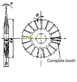
1.2 comb thread milling cutter
Comb thread milling cutter can be regarded as a combination of several disc thread milling cutters, as shown in Figure 2. During machining, the milling cutter is parallel to the axis of the workpiece, and the milling cutter is in contact with the workpiece along the full length of the thread. Therefore, when cutting, the workpiece rotates for one cycle, and the workpiece and milling cutter move a pitch relative to the axial direction, that is, the required thread can be cut out;
Comb thread milling cutter is mainly used to process triangular internal and external cylindrical threads and conical threads with short length and small pitch.
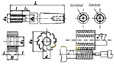
1.3. Compound thread milling cutter
In order to improve the production efficiency and cut out the thread at one time without changing the cutter, the composite thread milling cutter thread drill milling cutter shown in Fig. 3 (a) can be used. The cutting edge of thread drilling and milling cutter looks like a tap on the surface. In fact, it is different from the tap. There is no spiral lift on the tool, and the spiral in processing is realized by the movement of the machine tool.

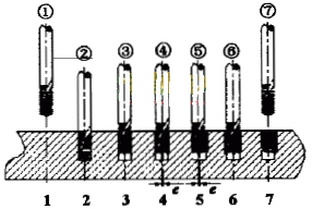
The working diagram of milling thread with thread drill and milling cutter is shown in Figure 3 (b). The steps are as follows: Step 1, the thread drill and milling cutter quickly runs to the safe plane of the workpiece; Step 2: drill the hole to the hole depth with the thread drill and milling cutter; Step 3: lift the thread drill and milling cutter to the thread depth; Step 4: the thread drill and milling cutter cuts the thread starting point with an arc; Step 5: the thread drilling and milling cutter makes interpolation movement in the X and Y directions around the thread axis and moves in the + Z direction parallel to the axis at the same time, that is, every 360 ° around the thread axis, a pitch will rise along the + Z direction, and the three-axis linkage motion trajectory of the cutter is a helix; Step 6: the thread drilling and milling cutter retreats from the starting point with an arc; Step 7: the thread drill and milling cutter quickly retreats to the safe plane of the workpiece and is ready to process the next hole. The motion track of thread milling with thread drill and milling cutter is shown in Figure 4:
2. Thread milling programming
Now M20 × 1.5 an example of right-hand internal thread milling illustrates the programming method of thread processing.
Workpiece material: cast iron; Diameter of threaded bottom hole: di18 38mm; Thread diameter: do = 20mm; Thread length: l = 25mm; Pitch: P = 1.5mm; Cutting tool: carbide thread drilling and milling cutter; Milling cutter diameter D2 = 10mm; Milling mode: forward milling; Cutting speed 50M / min; Milling feed rate: 0.1mm/tooth.
2.1 parameter calculation
Spindle speed: n = (1000V) / (d2p) = (1000) × 50)/(10×3.14)=1592(r/min)
The number of teeth of the milling cutter is Z = 1, the feed rate of each tooth is f = 0.1mm, and the feed rate at the cutting edge of the milling cutter is:
v1=fzn=0.1 × one × 1592=159.2(mm/min)
The center feed speed of milling cutter is: V2 = V1 (d0-d2) / d0 = 159.2 × (20-10)/20=79.6(mm/min)
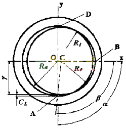
Set the safety distance CL = 0.5mm, and the cutting arc radius is:
Re=(Ri-CL)2+R02=(9.19-0.5)2+102=8.782R02 × ten
The cutting arc angle is: B = 180 ° – arcsin [(RI CL) / re) = 180 ° – arcsin [(9.19-0.5) / 8.78] = 180 ° – 84.12 ° = 95.88 °
Z-axis displacement when cutting into arc: Za = PA / 360 ° = 1.5 × 90°/360°=0.375(mm)
The coordinates of the starting point of the cutting arc are:
{ X=0
Y=-Ri+CL=-9.19+0.5=-8.68
Z=-(L-Za)=-(25+0.375)=-25.375
3. Thread milling program (Funuc system)
%
N10 G90 G00 G57 X0. Y0.
N20 G43 H10 Z0. M3 S1592
N30 G91 G00 X0. Y0. Z-25.375
N40 G41 D60 X0. Y-8.68 Z0.
N50 G03 X10. Y8. 68 Z0. 375 R8. 78 F79. six
N60 G03 X0. Y0. Z1. 5 I-10. J0.
N70 G03 x-10 Y8. 68 z0 375 R8. seventy-eight
N80 G00 G40 X0. Y-8.68 Z0.
N90 G49 G57 G00 Z200. M5
N100 M30
Related Posts


