
Study on deep hole machining technology of aviation hydraulic shell
Abstract: the main valve sleeve hole of shell parts in aviation hydraulic products has the characteristics of large length diameter ratio. This kind of parts are mainly made of high-strength aluminum alloy. The inner hole processing belongs to typical deep hole processing. Its dimensional tolerance, geometric tolerance and other requirements are strict, the surface roughness value is low, and there are many restrictions on the structure of machining tools, which brings great difficulties to the finish machining of parts. By studying the process route arrangement, processing parameters and processing tool selection of shell deep hole processing, and through many tests of various processing methods such as boring, grinding and honing, reaming processing is finally selected to ensure the processing accuracy requirements of shell deep hole, which solves the processing bottleneck of more than ten military key models of large-size hydraulic shell parts, which can be used as a reference for similar shell deep hole processing.
Key words: shell; Deep hole; Reamer
Generally, the hole whose ratio of depth to diameter is more than 5 is called deep hole. In the process of deep hole cutting, because the tool cuts inside the workpiece, the tool and cutting conditions can not be observed, and the tool is slender, the stiffness is poor, the cooling is difficult, and the chip removal is not smooth, so deep hole cutting is a difficult processing technology. The key technology of deep hole machining is the selection of tool parameters and the control of machining allowance
The hole diameter of the main valve sleeve hole of shell parts in aviation hydraulic products is 18 ~ 40mm, and the length diameter ratio is about 8 ~ 15. The material of this kind of parts is mainly high-strength aluminum alloy. Inner hole processing belongs to typical deep hole processing. Its dimensional tolerance and geometric tolerance are strict, the surface roughness is low, and there are many restrictions on the structure of machining tools, which brings great difficulties to the finish machining of parts.
1. Hydraulic housing parts
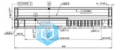
The part structure diagram of the hydraulic shell is shown in Figure 1. The surface roughness of the inner hole of the inner valve sleeve hole ∅ 29 + 0.0250 and ∅ 27 + 0.0250 mm is required to be Ra0.4 μ m. The allowable deviation of cylindricity is 0.008mm. The material of the part is forged aluminum alloy.
2. Process route
The part is processed on the horizontal machining center (machine tool model dixi-200), and the operating system is fanuc15 system (the macro program part of this method is common on FANUC-0i system). After many tests of various processing methods such as boring, grinding and honing, reaming is finally selected to ensure the geometric tolerance requirements of each inner hole of the part. Before machining in this process, the part is in the state of all inner holes to be machined, and 2mm Allowance [1-2] is reserved in the diameter direction.
Taking the 29 + 0.0250mm hole in Fig. 1 as an example, the processing process route is as follows: 1) milling the guide hole with a depth of 20mm and a diameter of 28 + 0.50mm at both ends; 2) Use ∅ 28mm flat bottom extended reaming milling cutter to process inner holes from both ends to < 28mm; 3) Boring from both ends to ∅ 28.8mm; 4) Boring from both ends to ∅ 28.92mm; 5) Boring and machining a guide hole with a diameter of 290-0.01mm and a depth of 50mm at one end; 6) Ream the guide hole with a depth of 50mm from ∅ 290-0.01mm to the drawing requirements at one time. Among them, step 5 is the key, which is beneficial to solve the trumpet shape of the orifice and the straightness of the hole. When reaming the inner hole with large length diameter ratio, the reamer rod must be thin and the rigidity is poor, so a lower cutting speed should be selected. After many tests, the spindle speed is 60R / min and the feed rate is 30mm / min (about 0.05mm per revolution and per tooth).
3. Selection and repair of reamer geometric parameters
3.1 selection of reamer geometric parameters
Generally, 6 ~ 8 cutting edges are selected for the reamer (see Fig. 2), and the shank is Morse 4 cone with pull nail structure. When the length diameter ratio of hole depth to diameter is greater than 10, the reamer taper parameter shall be increased, and the specific value is 0.04mm taper at about 50mm in the diameter direction.
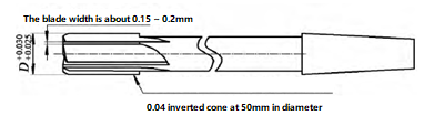
Take the machining of φ 29 + 0.0250mm hole in Figure 1 as an example. In horizontal machining, when the reamer is about to come out of the head, the coolant can not enter the machined inner hole, and the chip in the reamer chip removal groove has reached the most state. Due to poor cooling effect, the friction between the reamer and the hole wall is intensified, and the reamer is heated and expanded. When the rigidity of the reamer shank is insufficient, the machine tool spindle will rotate at a uniform speed and the reamer blade will rotate intermittently, which is reflected in the regular petal shape of the orifice at the outlet end of the inner hole on the part. The friction between reamer and hole wall is also related to the width and sharpness of reamer blade. The width of the edge band shall be 0.15 ~ 0.2mm, and the requirements shall be clearly specified in the tool drawing.
3.2 repair and grinding of reamer diameter
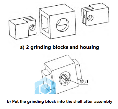
The split reamer grinder is composed of two grinding blocks and put into the shell (see Figure 3). When repairing and grinding, insert the reamer. When the reamer rotates, apply pressure from both ends and move back and forth along the axis of the reamer, which can easily control the diameter of the reamer.
Grindable open reamer 3 is also used. The opening direction of the opening grinding sleeve is: 1) the straight opening is suitable for left-hand and right-hand reamers; 2) The right-hand opening is suitable for left-hand and straight tooth reamers; 3) The left-hand opening is suitable for right-hand and straight tooth reamers.
The repair and grinding of reamer diameter is a key step in deep hole machining. The reamer diameter is made according to the deviation of the inner hole diameter of the machined part. After repair.
After reaming with the reamer, the surface roughness of the part can reach ra0.1 ~ Ra0.2 μ m。 The inverted cone of reamer shall also be trimmed manually. When the reamer has shrinkage (shrinkage refers to that the diameter of the hole is smaller than the diameter of the reamer after reaming), a small amount of shrinkage is good for the machining surface quality, but it will increase the tool torque. When the shrinkage is greater than 0.015mm, the reamer should be replaced.
4. Setting of part working coordinate system and rational use of system variables
Since the machine tool used for machining is a horizontal four-axis machining center, the machining of inner holes shown in Figure 1 can be easily completed by rotating the machine turntable in one clamping, and the machining of such parts often requires three working coordinate systems. Suppose one is the angular datum, which is set as g56, and the other two are the coordinate systems g54 and G55 machined at both ends respectively. The relationship between the three working coordinate systems is that g54 and G55 differ by 180 °, and g54 and G55 differ by ± 90 ° from g56 respectively. The Y coordinates of g54 and G55 are the same, while the values of X coordinates are the same and the signs are opposite. Use the macro program system variable to change the working coordinate system. After the probe corrects g56 angular reference and g54x reference, run the following macro program section:
5241 = – the x value of 5221g55 coordinate system is equal to the – x value of g54 coordinate system
5224 = the angle value of 5264-90g54 coordinate system is equal to g56 angle datum – 90 °
The angle value of 5244 = 5264 + 90g55 coordinate system is equal to g56 angle reference + 90 °
It can be seen from the above program section that all working coordinate systems required for workpiece processing can be input by macro program without any human input, which completely avoids the possibility of human error [4-5].
5. Conclusion
The deep hole machining of length diameter ratio has always been a difficult problem in machining, especially when each step hole in this paper has geometric tolerance requirements such as coaxiality and cylindricity. For processing programming, we should not only consider whether the program is correct or not, but also reduce the difficulty of the operator and the probability of human error as much as possible. When machining deep holes, it is difficult to achieve the ideal effect only by some improvement such as tool parameters or machining program. A reasonable machining method should comprehensively consider the optimization of machining steps, tool geometric parameters, tool cutting parameters and machining procedures.
After many tests of various processing methods such as boring, grinding and honing, reaming is finally selected to ensure the size requirements of each inner hole of the parts, and solve the processing bottleneck of more than 10 Military key models of large-size hydraulic shell parts.
Related Posts


