Challenges and solutions in machining metal 3D printing parts
Many 3D printed metal parts need to be machined to produce precise surfaces, but 3D printed parts are often lightweight parts with complex geometry, which brings challenges to subsequent machining. When machining 3D printing parts, we need to consider a series of problems, such as whether the stiffness of 3D printing meets the requirements of machining, and how to clamp these complex 3D printing parts with fixtures. Through a 3D printing metal parts machining case shared by additive manufacturing experts, we jointly discuss the challenges and solutions in 3D printing parts machining.
3D printing is a flexible technology with less constraints on design. With the help of 3D printing technology, designers can realize some complex design schemes, such as lightweight structure and integrated structure of function integration. However, these advantages of additive manufacturing technology are sometimes weakened by taking into account the challenges in subsequent machining. If the challenges faced in subsequent machining are not fully considered in the initial design and manufacturing of additive manufacturing parts, losses may occur due to the failure of part processing.
3D printed parts usually need to be machined to achieve accurate circular holes and smooth and flat surfaces, and then assembled with other parts. However, the complex lightweight structure of 3D printing parts sometimes can not adapt to the machining process because of insufficient stiffness. In addition, the complex structure also increases the difficulty of safely clamping the workpiece.
Finishing challenges
1. Whether the rigidity of 3D printing parts is enough to meet the load borne during machining? Does the part deviate from the tool and produce vibration, which makes the tool vibrate and leads to poor machining effect? If the stiffness of 3D printed parts is not enough to meet the requirements of machining, what solutions can solve these problems?
2. If the problem of stiffness is solved, the next challenge is how to align on the machine tool. 3D printed parts may have some deformation and lack of clear benchmark during printing, which means that when machining 3D printed parts, it is necessary to first find the “good” part of the parts. It is very important to obtain the optimal 5-axis alignment of parts.
Renishaw explored the challenges and solutions faced in the finishing of 3D printing parts through a metal 3D printing microwave guide rod. There are a total of 9 steps from the preparation before machining to the final finishing of parts.
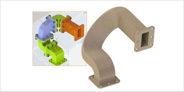
The figure on the left shows the guide rod made with traditional design ideas and manufacturing methods, which is assembled from several parts; The right figure shows the 3D printed guide rod, which is an integrated part. Compared with the original part, the weight is reduced by half. This is a part designed for telecommunication satellite. The main performance requirements of this part are to lighten the weight, improve the propagation efficiency of microwave, and reduce the space requirements of the part for satellite payload.
Solution
Step 1: establish the expected cutting force
First, experiments are conducted to evaluate whether 3D printed parts have sufficient stiffness required by machining.
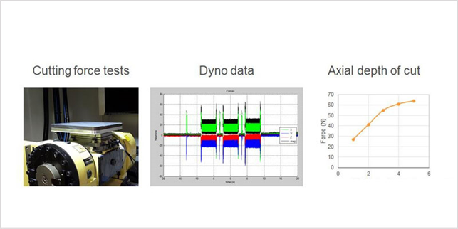
Dyno data shows the repeated load, and it can be seen that the peak force is about twice the middle value. You can also try cutting at different depths to understand how it affects the load on the part.
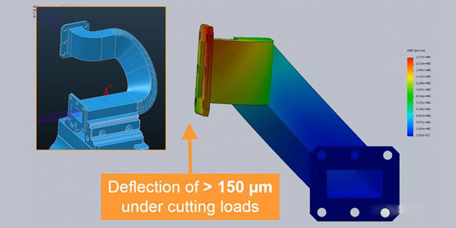
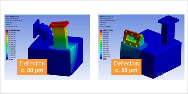
Step 2: simulate cutting force
Through the simulation process, it is found that the flange edge machining around the free end of the part leads to obvious deflection (greater than 150 microns), and the finite element analysis also shows obvious distortion, which may lead to uneven cutting.
Step 3: initial cutting test
If machining is carried out under the above circumstances, the parts will deviate from the tool and rebound, surface vibration, tool vibration and other problems will be encountered. The result of these problems is a poor surface finish.
The way to solve these problems is to improve the stiffness of parts in the cutting process. There are two steps to improve the stiffness: one is to adjust the design of 3D printing parts, and the other is to change the clamping mode in the machining process. First, let’s learn how to solve these problems by adjusting the design.
Step 4: meet the challenges of machining by changing the design of 3D printed parts.
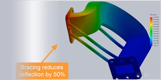
The goal of changing the design of 3D printed parts is to make the parts harder. In this case, the designer uses the method of adding a support structure connecting the components at both ends of the parts to reduce the defects seen in the cutting test.
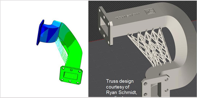
Or add a truss structure connecting components at both ends, which is more complex. The disadvantage of adjusting the design scheme to improve the stiffness is that it increases the volume occupied by the parts, which may affect the space occupied by other components and reduce the overall efficiency of the design. Another noteworthy problem is that under the conventional workpiece clamping mode, the parts adjusted and designed often still can not meet the machining requirements. At this time, it is necessary to reconsider the clamping mode of parts.
Step 5: reconsider the clamping method of parts
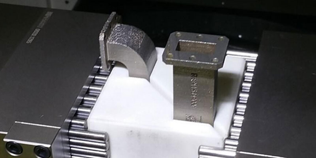
In this case, the specific scheme of re clamping method is to design a customized fixture for 3D printing parts, and directly manufacture the customized fixture with 3D printing equipment, which reduces the risk of part deformation and surface damage, makes 3D printing parts closer to processing features, and reduces deflection and vibration.
Step 6: model the customized fixture
During the finite element analysis of the 3D printed parts in the fixture, the designer found that the stiffness can be further improved by better clamping the “straight” structure in the parts.
Step 7: Machining preparation
After completing the design and adjustment of 3D printing parts and the design and manufacture of customized fixtures, you can enter the preparation stage of machining.
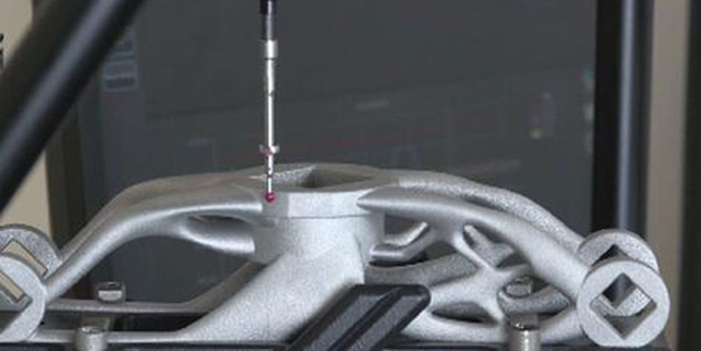
The figure shows a topologically optimized 3D printed part measured on a flexible gauge to produce a 5-axis alignment for subsequent machining.
In this process, errors occur when the linear and rotational motion of the mechanical shaft exceeds the tolerances required to manufacture accurate parts. In this case, the engineer used Renishaw contact probe and measurement software NC checker to identify and monitor these problems.
Step 8: Part setup
In conventional machining, datum planes are often created first, and then these features are used to align and locate parts for subsequent machining operations. However, for the 3D printed parts in this case, the conventional method is not followed, because the accuracy benchmark must be added to the final machining operation after generating all other surfaces.
The challenge of 3D printing part setting is to set it through the actual shape of the part, which involves understanding the material condition of the part in all areas where precision features are planned to be cut, taking into account factors such as machining allowance and part deformation. In this case, the designer seeks to leave enough material in all these locations to allow consistent and effective cutting. In this step, the probe and metering software can still be used to find the “best fit” setting of finishing.
Another way to set up a finished 3D printed part is to measure the part and perform alignment using workshop programmable specifications. This method is more suitable for larger batch applications.
Step 9: Machining
Through the preparation of the above eight steps, the resulting components have critical dimensions within the tolerance range and show good surface finish. Compared with early machining and cutting tests, tool vibration and wear are greatly reduced.
Machining is usually a part of the metal 3D printing process chain, which is also a process with war escape and risk. If machining fails, it will lead to the scrapping of a valuable 3D printing part. If the challenges faced in machining can be considered at the beginning of designing 3D printed parts, it will help to reduce the risk of failure.
Related Posts


