How to use FDM technology to create variable density parts?
FDM (fused deposition molding) technology is one of the most common 3D printing technologies, but it can be used not only for desktop level equipment, but also for industrial level equipment. As the inventor of this technology, Stratasys has shared some technical dry goods for the application of FDM 3D printing technology in industry.
Now let’s learn how to use industrial grade FDM 3D printing technology to print parts with variable density. Moreover, if the operation mode is proper, FDM technology can also greatly save time and cost. How to operate it best? See below:
Step 1: Introduction
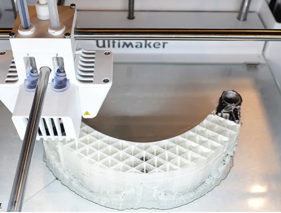
The unique feature of FDM technology is that its single part can have areas with different construction styles to make parts with variable density. Different from the preset style of the system, solid or sparse will be applied to the whole part. Variable density allows a single part to be composed of solid and sparse fill patterns, and the density of each area can be adjusted independently.
Only a few minutes of additional design and preprocessing can save hours of construction time and greatly improve part attributes.
The advantages of variable density parts include:
1. Optimize strength, weight and performance
2. Shorten construction time and cost
3. Enable advanced applications (such as end parts, fiber forming, and thermoforming)
4. Adjust the center of gravity of parts (for example, use a smaller motor to run a larger mechanical arm)
Use 3D computer aided design (CAD) and Insight software to jointly create variable density parts. In order to fully control each area, the 3D CAD model is divided into sub components, and each model may have a unique density. Each sub component has a different tool path selection.
Variable density is often used when optimizing design functions. For example, solid fill is used when additional strength is required, while the rest of the part is constructed with sparse fill.
You will need to:
1. 3D computer aided design (CAD) software
2. Insight software (Insight 9.0)
Step 2: Modify CAD model
Open the CAD model for variable density production.
Add a reference feature (square aluminum) at the origin so that it is slightly higher than the part. This will help to strengthen the consistency of various regions within Insight software.
Extract a sub area and reference feature from the complete CAD model, and then delete the balance of the model.
The offset surface fits with the main structure to create a 0.03 mm (0.001 in) gap. Export this file as an STL file. Reopen the original CAD file and extract the next area. As in the first area, the reference elements are retained when the balance of the model is deleted.
Repeat the above steps until all the required areas are created.
Step 3: Use Insight software to process areas
Configure Modeler. Open and adjust the STL file to confirm that the reference feature is at the origin. Creates a part curve using the current parameters. From the Tool Path menu, select Custom Group. Click New to create a new custom group and adjust the parameters to achieve the desired features for that area. For example, change the part interior style to double density sparse fill through a custom group.
Click the green hook symbol to confirm the selection. Use the cursor to select the desired curve and click Add. All curves added to this group will have the tool path parameters you defined. Save the job. Repeat the above steps for all areas except the last one.
Open, adjust, and split the last STL file, and then use the custom group to apply the desired tool path. Save the job and keep it open. Click the Merge Slice Curves file in the Slice drop-down menu, and then import the subregion into the job.
Locate the sub region in the job by entering the slice curve position (0,0,0). The reference feature will ensure that all areas are properly aligned.
Use the Delete operation in the Edit drop-down menu to select and delete the curves of all reference features. Save the job.
Step 4: Conclusion
With the above operations, you can create parts with different densities at will, and save time in constructing or improving part attributes.
Related Posts


