Use method of lathe and tool rest and installation method of tool rest
Tool holder is the simplest automatic tool changing device of lathe, and it is also a very important component. The structural form of the tool rest is generally rotary. The tool is installed on the tool rest along the circumferential direction, and radial turning tools, axial turning tools, drill bits and boring tools can be installed. The turning center can also be equipped with axial milling cutter and radial milling cutter. The tool rest of a few CNC lathes is in-line, and the tools are installed along a straight line. Next, the quick screen editor will introduce the use method of the lathe and the tool rest and the installation method of the tool rest. Let’s learn about it!
Use method of lathe and tool rest:
1. The center frame is fixed on the guide rail of the bed and has three independently movable supporting claws, which can be pre fixed with fastening screws. When using, install the workpiece on the front and rear centers, finish turning a section of smooth surface on the workpiece support part, then fix the center frame at the proper position of the guide rail, and finally adjust the three support claws to make them contact with the workpiece support surface, and adjust to the appropriate tightness.
2. The use of the center frame can improve the cutting performance of the workpiece during the turning process. However, since the workpiece is turned in two sections, there are tool receiving traces in the middle of the workpiece. The lathe shall adopt the method of following the tool rest for the workpiece that is not allowed to have tool connection. The lathe and the tool rest are fixed on the bed saddle and move longitudinally together with the turning tool.
3. The following tool rest is fixed on the side of the carriage and moves longitudinally with the tool rest. The tool holder has two supporting claws, which closely follow the turning tool and play an auxiliary supporting role. Therefore, the heel rest is mainly used for the processing of slender optical axis. To use the tool holder, first turn a section of outer circle at the right end of the workpiece, adjust the position and tightness of the two support claws according to the outer circle, and then turn the full length of the optical axis. When using the center frame and the tool holder, the rotation speed of the workpiece should not be too high, and the support claw should be filled with oil for lubrication.
4. There are two claws and three claws with the lathe tool rest. When the lathe adopts two claw tool rest, the cutting resistance of the turning tool to the workpiece makes the workpiece cling to the two supports of the tool rest. When the lathe is actually used, the workpiece itself has a downward gravity, which will make the workpiece bend naturally. Therefore, during turning, the workpiece often leaves the support claw instantaneously due to centrifugal force and contacts the support claw to generate vibration. Therefore, when turning the slender shaft, it is better to use the three claw tool rest, because the tool rest with three supporting claws can make the workpiece move up, down, front and back, and the turning is stable and it is not easy to generate vibration.
5. When using the tool holder, it is necessary to pay attention to the proper tightness of the support claw to the workpiece. If it is too loose, it will not improve the rigidity. If it is too tight, it will affect the shape accuracy of the workpiece. The workpiece turned out is “bamboo shaped”. During the turning process of the lathe, the tightness of the support claw shall be frequently checked and necessary adjustments shall be made.
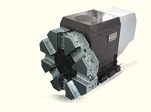
The rotary tool rest is a typical tool change tool rest most commonly used in CNC lathes. Generally, the automatic tool change action of the machine tool is realized through the hydraulic system or the electric system. According to the processing requirements, it can be designed as a square, hexagonal or disc tool rest, and 4, 6 or more tools are installed correspondingly. It is impossible to install too many tools on the row tool holder and the rotary tool holder. Even if two tool holders are equipped, there is a certain limit on the number of tools. When a large number of tools are required for some reason, the automatic tool changing device with tool magazine shall be used.
Installation method of tool rest:
1. Installation of vertical tool rest
(1) Disassemble the guide rail insert and pressing plate on the tool holder, clean the guide rail and the processing surface, and check whether the guide rail surface is intact and free of rust.
(2) The left and right vertical tool holders shall be hoisted and installed on the beam respectively, and the guide rail surface shall be coated with lubricating oil. The gear of the tool holder moving and driving shall be aligned with the assembly hole of the beam, and the pressing plate and inlay shall be installed to adjust the clearance of the guide rail.
(3) Install the bottom shaft of the vertical tool rest lifting, remove the pressing member of the counterweight, and make the counterweight balance.
2. Installation of side cutter holder
(1) Remove the inlay and pressing plate, clean the guide rail and other processing surfaces, and apply lubricating oil after inspection.
(2) The protective paint shall be removed from the connecting parts between the tool rest and the counterweight, such as bearings, pulleys (or sprockets), axles, hanging cables or chains.
(3) Put a square wood on the f part of the front face of the vertical calibration, clean the guide rail surface of the vertical calibration, apply lubricating oil, hang the side tool holder upright, slowly approach the front guide rail of the vertical calibration, install the inlay and pressing plate, preliminarily adjust the guide rail clearance, and connect the lifting mechanism.
(4) Connect the counterweight with the side tool rest, lift the tool rest by hand, check whether there is jamming, and remove the square wood.
Related Posts


